ICPDAS I-7530A-MR
Modbus RTU to CAN converter
● RoHS Design
● Fully compatible with ISO 11898-2 standard
● Programmable CAN bus baud rate from 10 kbps to 1 Mbps or user-defined baud rate
● Support CAN bus acceptance filter configuration
● Support firmware update via RS-232
● Provide utility tool for module setting and CAN bus communication testing
● Built-in jumper to select 120Ω terminator resistor
● CAN buffer: 128 data frames ; UART buffer: 256 bytes
● Power, data flow and error indicator for CAN and UART status
● Hardware Watchdog design
● Convert CAN message to specific ASCII command string (Normal mode)
● Convert specific ASCII command string to CAN message (Normal mode)
● Provide the transparent communication between the RS-232/485/422 devices via CAN bus (Pair-connection mode)
● Support function code 0x03/0x04/0x10 of Modbus RTU command for reading and writing CAN message (Modbus RTU mode)
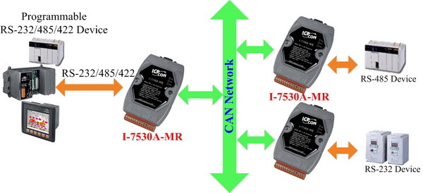
The I-7530A-MR is helpful for data exchanging between the RS-232/485/422 devices and the CAN devices. It supports three communication modes: “Normal”, “Modbus RTU”, “Pair-connection”.
In the Normal mode, the I-7530A-MR is designed to unleash the power of CAN bus via RS-232/485/422 communication method. It accurately converts ASCII format messages and CAN messages between RS-232/485/422 and CAN networks. This mode let you to communicate with CAN devices easily from any PC or programmable devices with RS-232/485/422 interface.
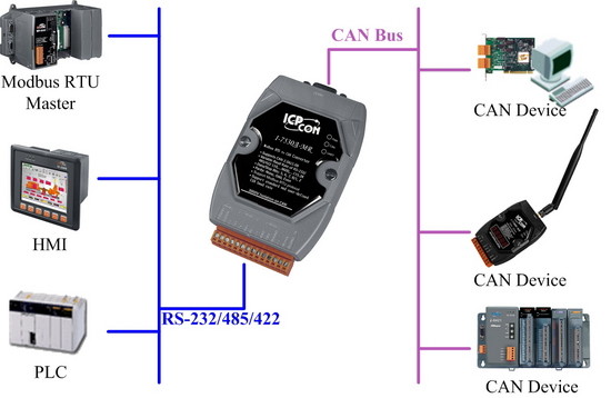
In Modbus RTU mode, it allows a Modbus RTU master to communicate with CAN devices on a CAN network. The following figure shows the application architecture of this mode.
In pair-connection mode, this module provides the transparent communication between the RS-232/485/422 devices via CAN bus. The application architecture may be as follows.
APPLICATIONS:
● Control System
● Building Automation
● Factory Automation
● Distributed Data Acquisition
| Controller | Microprocessor inside with 96 MHz |
| Transceiver | NXP 82C250 |
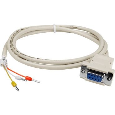
| Connector | 9-pin male D-Sub (CAN_L, CAN_H, N/A for others) |
| Channels | 1 |
| Baud Rate (bps) | 10 k, 20 k, 50 k, 100 k, 125 k, 250 k, 500 k, 800 k and 1 M (allow user-defined baud rate) |
| Protection | 3000VDC power protection and 3750Vrms photo-couple isolation on CAN side |
| Terminator Resistor | Selectable 120Ω terminator resistor by jumper |
| Support Protocol | ISO-11898-2, CAN 2.0A and CAN 2.0B |
| Pin Assignment | C.I.A. DS-102 (CAN_H=7, CAN_L=2) |
| Connector | 14-pin terminal connector | |||
| COM |
|
|||
| Baud Rate (bps) | 300,600,1200, 2400, 4800, 9600, 19200, 38400, 57600, 115200, 230400 | |||
| Protection | 3000VDC power protection and 2500Vrms photo-couple isolation on UART side |
| Round LED | PWR/CAN/UART |
| Power Supply | +10 ~ +30 VDC |
| Power Consumption | 1.5 W |
| Dip Switch | Init (Firmware Update, Module Configuration)/Normal (Firmware Operation) |
| Installation | DIN-Rail Mounting |
| Dimensions (w x l x h) | 72 x 118 x 35mm |
| Operating Temperature | -25 °C ~ 75 °C |
| Storage Temperature | -30 °C ~ 80 °C |
| Humidity | 10 ~ 90% RH, non-condensing |