RS-232/RS-485 to Parallel Digital Interface OEM Board
● Provides a user-definable parallel interface with bit, byte and string data transfer capabilities. Fully configurable to the user's needs by bus commands. ● Signal monitor feature detects signal changes. Relieves controller of time consuming polling function. ● High-current drivers and input pullup resistors. Drives larger loads and inputs CMOS signals or contacts. ● Programmable RS-232 and RS-485 serial interfaces. Supports point-to-point or network connections. ● Provides IEEE-488.2 Status Structure and SCPI parser. GPIB functionality over a serial link. ● Device setup and network address stored in Flash. Stored setup eliminates program initialization statements. ● Includes a menu-driven configuration program. Steps user through configuration choices.
GPIB to Parallel Digital Interface Board provides 48 high-power TTL type digital I/O signals with same pinouts as the Model 4863 Minibox. Internal power supply runs on 9 to 32 Vdc. On-card header connects to ICS's GPIB Connector/Address Switch Assemblies to mount a GPIB Connector and an Address Switch on the rear panel.
Provides RS-232 full duplex and RS-485 (RS-422) half duplex asynchronous serial interfaces. Unit automatically responds to the serial interface that receives the command.
RS-232 Interface
Signals
AB, BA and BB
Mode
Full Duplex
RS-485 (RS-422) Signals
Signals
TX/RX pair
Mode
Half duplex with or without address detection
Addresses
0 ~ 15
Termination
220 Ω load resistor and 1 KΩ pullup/pulldown resistors
Data Rates and Formats
Baud Rate
1200 ~ 115.2 Kbaud
Data Bits
7 or 8
Stop Bits
1 or 2
Parity
Odd, Even or None
Command Sets
SCPI and short form commands plus the following IEEE 488.2 Common Commands:
2363's parallel I/O signals have the following electrical characteristics. All time delays listed here are maximums, all pulse widths are minimums.
Lines
48 Digital I/O plus 2 Status Inputs
Input Logic Levels
High = > +2.0 V @ ±10 μA
Low = <0.8 V @ 250 μA
with 33 KΩ pullup to +5 VDC for sensing contacts
Max High = 5.5 V
Input Timing
External Data Inhibit line SETS within 1 μs of the active edge of the EDR Input signal and resets after data is loaded. Data loading time for 6 BCD/HEX characters is 0.15 ms (typ.) after the 2363 has been addressed as a Talker.
Output Logic Levels
High = >3 V with 3 mA source
High =>2 V with 24 mA source
Low = 0.0 to +0.55 Vdc, 48 mA sink
Output Timing
Data is transferred to the output 0.7 to 6 ms after receipt of a terminator depending upon transfer method.
Data Stb
Output pulse width, 7 μs
Trigger
Output pulse width, 7 μs
Clear
Output pulse width, 7 μs
Reset
Output pulse width, 50 μs for
*RST command and true during 2363 reset time (70 ms)
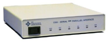
Controls and Indicators
Controls
POWER
Front-panel switch energizes unit
Indicators
PWR
Indicates power on
RDY
Unit has passed self test
TX
Unit is transmitting
RX
Unit is receiving
SRV
Unit sent Service Request Message
ERR
Unit has detected a command error
Grootte
1185.2 x 38.6 x 189.2mm (W x H x D)
Connectors and Headers
Serial
25-pin female, metal DB shell with lock studs
I/O
62-pin female, metal DC shell connector with lock studs
Serial Header
10-pin male
LED Header
8-pin male
Omgeving
Operating Temperature
-10 °C to +55 °C
Storage Temperature
-40 °C to +70 °C
Humidity
0-90% RH no condensation
Power
9 to 32 VDC @ 3 VA
Mechanical
Construction
All metal case shields RFI
Included Accessories
Instruction Manual
Configuration Disk
UL/CSA/VDE/CE approved AC power adapter
Mating 62-pin connector and hood