ICPDAS I-8088W
8-channel PWM Output And 8-Channel isolated DI Module
● Automatic generation of PWM outputs by hardware, without software intervention.
● 10Hz ~ 500kHz (non-continuous) PWM output frequency with 0.1% ~ 99.9% duty cycle
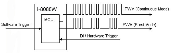
● Software and hardware trigger mode for PWM output
● Individual and synchronous PWM output
● Using software trigger mode, you can set configuration for all PWM channels then trigger them one by one or all of them at the same time.
● Burst mode PWM operation for standby
● DI channel can be configured as simple digital input channel or hardware trigger source of the PWM output.
PWM (Pulse width modulation) is a powerful technique for controlling analog circuits. It uses digital outputs to generate a waveform with variant duty cycle and frequency to control analog circuits. I-8088W has 8 PWM output channels and 8 digital inputs. It can be used to develop powerful and cost effective analog control system.
With different communication interface, the I/O modules can be classified to high communication speed (Parallel bus) 8K series modules and low communication speed (serial interface) 87K series modules.
| There are two types of I/O modules, Parallel and Serial. The parallel modules (I-8 Series) are high-speed modules and support MCU (Main Control Unit) only. | |
| Item | I-87K Series |
| Communication Interface | Parallel Bus |
| Protocol | - |
| Communication Speed | Fast |
| DI with Latched Function | - |
| DI with Counter Input | - |
| Power On Value | - |
| Safe Value | - |
| Programmable Slew-rate for AO Module | - |
High Profile VS Low Profile
With different form factor, I/O modules can be classified to high profile and low profile. Basically, high profile and low profile modules that with same item number also have same I/O channel number.
For example: I-8054 and I-8054W both has 8 DI and 8 DO.
Except I/O channel number, other specifications could be different. You have to double check whether the specifications suit your application.
For example: For I-8054W, its DI logic high level is +10 ~ +50V. But for I-8054, it is +3.5 ~ +30V
APPLICATIONS
● Controlling the position/speed of motors
● Dimming the brightness of lamps
● Controlling the speed of fans
| Channels | 8 |
| Scaling Resolution | 16-bit (1 ~128 μs for each step) |
| Frequency Range | 10 Hz ~ 500 kHz (non-continuous) |
| Duty Cycle | 0.1% ~ 99.9% |
| Burst Counter | 1 ~ 65535 |
| Hardware Trigger Mode | Trigger Start & Trigger Stop |
| Output Type | Source |
| Max. Load Current | 1 mA |
| Intra-module Isolation, Field to Logic | 3750 Vrms |
| ESD Protection | 4 kV Contact for each channel |
| Input ChannelsChannels | 8 (Sink/Source) |
| Input Type | One Common for All Digital Input |
| On Voltage Level | +5 V ~ +30 V |
| Off Voltage Level | <0.8 V |
| Input Impedance | 4.7 kΩ, 0.25 W |
| Intra-module Isolation, Field to Logic | 3750 Vrms |
| ESD Protection | 4 kV Contact for each channel |
| 1 LED | Power Indicator |
| 16 LEDs | PWM and Digital Input Indicator |
| Power Consumption | 40 mA@5 V, 2 W ±5% |
| Dimensions (w x l x h) | 30 x 102 x 115 mm |
| Operating Temperature | -25 °C ~ +75 °C |
| Storage Temperature | -30 °C ~ +85 °C |
| Humidity | 5 ~ 95% RH, Non-condensing |